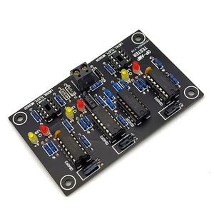
Feature Common single op amp and dual op amp Screening circuit board finished boards the circuit board can judge whether the IC can be used for amplification and can roughly judge the conversion rate of the chip IC1a in the circuit is connected to a multivibrator with a frequency of about 1Hz and the OP Amp to be tested is connected to a unity gain inverting amplifier working state IC2 is an EX OR gate and its truth table is that the output is 1 when the two inputs are inverted The original design D3 is green because the solder mask of the printed board is green and not eye catching so it is changed to a yellow LED For chips with a low conversion rate the status indicated by the LED is steady yellow and red will flicker faintly This can also be used to roughly judge the conversion rate of the chip Because most of the motorcycle chips on the market use low conversion rate instead of high rate it can also be judged whether the chip is cheap or not Therefore after power on there are the following situations If OP Amp is normal points A and B of IC2 must be reversed so C is 1 and it is still 1 after IC1b and 1d so D3 of the yellow LED lights up and the red LED goes outIf the OP Amp output is open the C point of IC2 must always be 0 and it will become 1 after IC1c so that the yellow LED is extinguished and the red LED D4 is lit If the internal short circuit of OP Amp makes the output voltage fixed to positive or negative the output of IC1c is also a 1H
Price history
Jul 21, 2022
€12.87

